Flow in Pipe Network Analysed Using Hardy Cross Method
| ✅ Paper Type: Free Essay | ✅ Subject: Physics |
| ✅ Wordcount: 1206 words | ✅ Published: 09 Mar 2018 |
Table of Contents
2.0 Procedure for Hardy Cross method:
3.0 Flow in Pipe Network analysed using Hardy Cross method
1.0 Introduction
Piping networks have quite a wide range of practical applications, from water and gas distribution systems to air conditioning installations. Although simple problems, such as for instance, a single branch connecting two reservoirs, may be solved analytically, more complex network problems need an iterative approach, recurring to a digital computer. The most popular method for solving this type of problems is the Hardy-Cross method. The Hardy Cross method is an iterative method for determining the flow in pipe network systems where the input and output flows are known, but the flow inside the network is unknown. Also, the pipe length, diameter, roughness and other key characteristics should be known. Before the method was introduced, solving complex pipe systems for distribution was extremely difficult due to the nonlinear relationship between head loss and flow.

Water distribution system models have become very important and practical tool for civil engineers. Models are often used to optimize the design of new distribution systems or analyze major extensions or modifications to existing distribution systems. The introduction of the Hardy Cross method for analyzing pipe flow networks revolutionized municipal water supply design (Pdhengineer.com, 2014).
The Hardy Cross method is normally used as the pipe network analysis by most engineers. Computer models help engineers to solve difficult situations, namely:
- What is the maximum fire flow at a given point in the system?
- How long can that fire flow be provided for?
- What size pipe installation would be necessary between two points in a system to increase the pressure at one of the points to the minimum pressure required?
- If a subdivision or commercial development is built, will adequate pressures and flows exist? If not, what length and size of water mains must be upgraded by the developer to allow for the proposed construction?
2.0 Procedure for Hardy Cross method:
This method is applicable to closed-loop pipe networks. The outflows from the system are assumed to occur at the nodes, where a node is the end of each pipe. This assumption would therefore result uniform flow in the pipelines distribution systems.
The Hardy-Cross analysis is based on the principles that
- At each junction, the total inflow must be equal to total outflow.
- Head balance criterion: algebraic sum of the head losses around any closed-loop is zero.

For a given pipe system, with known junction outflows, the Hardy-Cross method is an iterative procedure based on initially estimated flows in pipes. Estimated pipe flows are corrected with iteration until head losses in the clockwise direction and in the anticlockwise direction are equal within each loop.
- A trial distribution is madearbitrarily but in such a way that continuity equation is satisfied at each juction.
- With the assumed value of Q, the head loss in each pipe is calculated according to the equation

Where
 : head loss
r : head loss per unit flow
n : flow exponent
- The net headloss around each loop is calculated.
- If the net head loss due to assumed values of Q round the loop is zero, then the assumed values of Q in that loop are correct. If this is not the case, then the assumed values of Q are corrected by including a correction ï„Q for the flows till the circuit is balanced.
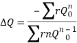
- The correction factor ï„Q is obtained by
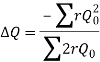
- For turbulent flow, the value of n=2 and hence the correction factor becomes
- If the value of ï„Q is positive, then it is added to the flow in the clockwise direction and subtracted from the flows in the anticlockwise direction.
- After the correction have been applied to each pipe in a loop and to all loops, a second trial calculation is made for all loops. This procedure is repeated till ï„Q becomes negligible.
3.0 Flow in Pipe Network analysed using Hardy Cross method
4.0 Advantages
- The Hardy Cross method is useful because it relies on only simple math, circumventing the need to solve a system of equations. Without the Hardy Cross methods, engineers would have to solve complex systems of equations with variable exponents that cannot easily be solved by hand.
- The Hardy Cross method iteratively corrects for the mistakes in the initial guess used to solve the problem. Subsequent mistakes in calculation are also iteratively corrected. If the method is followed correctly, the proper flow in each pipe can still be found if small mathematical errors are consistently made in the process.
- This method is based on the successive addition of flow-rate corrections in each branch, in order to achieve satisfaction of energy conservation along every path in the network.
- The easiness of building a new network or modifying an existing one allows the engineer to readily observe how small changes in the network configuration may produce interesting results such as a flow reversal in a certain branch.
5.0 Conclusion
Distribution system is a network of pipelines that distribute water to the consumers. They are designed to adequately satisfy the water requirement for a combination of domestic, commercial, industrial and fire fighting purposes.
In any pipe network, the algebraic sum of pressure drops around a closed loop must be zero (there can be no discontinuity in pressure) as well as the flow entering a junction must be equal to the flow leaving that junction; i.e. the law of continuity must be satisfied (Nptel.ac.in, 2014).
A good distribution system should provide adequate water pressure at the consumer’s taps for a specific rate of flow. The pressures should not only be great enough to adequately meet fire fighting needs, but should also not be excessive due to pressure leakages which is cost-effective. However, in tall buildings, booster pumps are required to elevate the water to upper floors. Moreover, distribution system of purified water should be completely water-tight and the purity of distributed water should be maintained. Maintenance of the distribution system should be easy and economical. Even, during breakdown periods of pipeline, water should remain available. If a particular pipe length is under repair and has been shut down, the water to the population living in the down-stream side of this pipeline should be available from other pipeline. The distribution pipes systems should not be placed under highways, carriage ways as they will obstruct any traffic flow, but should be laid under foot paths.
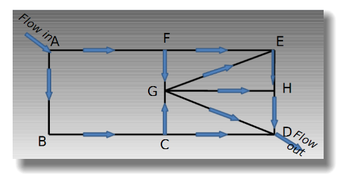
Figure 1: Pipe network for Municipal water distribution systems in cities (Scribd.com, 2014)
Cite This Work
To export a reference to this article please select a referencing stye below:
Related Services
View all


DMCA / Removal Request
If you are the original writer of this essay and no longer wish to have your work published on UKEssays.com then please click the following link to email our support team:
Request essay removal