Effect of Battery Voltage on Output
| ✅ Paper Type: Free Essay | ✅ Subject: Physics |
| ✅ Wordcount: 1708 words | ✅ Published: 01 Feb 2018 |
Andy Nguyen
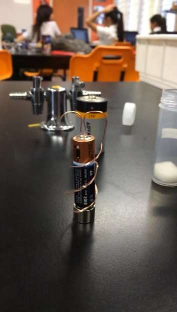
Table of Contents
1.3 Materials & Risk Assessment
1.0 Introduction
The homopolar motor device or also known as unipolar motors are commonly used in everyday society. For example, it can be related to an electric circuit in cars or in high torque wind turbines. But in this case, the homopolar motor consists of an AA battery, copper wire and a neodymium magnet. The aim of this experiment only using this setup is to see how the voltage of the battery affects the number of times the wire revolves around the battery and magnet. It was hypothesised that the larger the voltage or battery, the longer it took to revolve around the battery as size is determining the current output.

1.1 Theory Review
The magnet used in this experiment is called a Neodymium also known as Neodymium-iron-boron. This is a rare earth magnet and is stronger than the average magnet. It has a high resistance to demagnetization and its energy content level is high. If these magnets are not carefully stored or used properly, it can have major effects on the magnet such as corroding or caught on fire if used in high temperatures. Like any other magnet, the Neodymium magnet has a North and South Pole and depending on which side it’s used, it affects the direction in which the wire is rotating.
Alkaline batteries are commonly used to make an electric device work. It contains chemical energy which then converts to electrical energy when placed in a device such as remotes and toys. An alkaline battery contains to electrodes, anode and cathode. Anode is an electrode through which electric current flows into a negatively polarized electrical device. A cathode is when the electrode flows out of the positively polarized electrical device.
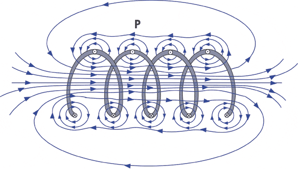
When electricity is run through a loop or coil of wire, the electricity has passed through a magnetic field, refer to appendix 3. The Neodymium magnet has both North and South Pole which attracts and repels the current flowing through the rotor thus creating a constant torque which leads to the loop of wire spinning. This repetitive attracting and repelling can go on continuously as long as a stable current goes through it.
To find out how the radius of the wire affects the speed of the revolutions, angular velocity must be found. Angular velocity can be considered as a vector quantity thus this unit is measured in radians per second. The formula for angular speed is:

Where  is the revolutions per minute and
  is the time taken in seconds. The formula is then multiplied by
  for the full circular motion unit for a circle is measured in radians.
Polarisation is when the charges inside a particular object is split and separated into each ends away from their distinctive other. A magnet for example, when polarised has two poles, where one end of the pole consists of positive charges whilst the other end will consist of negative charges. This concept determines the direction at which objects rotate.
1.2 Hypothesis
It was hypothesised that the bigger the radius of the wire, the slower the angular speed will be. But as the voltage is increased using the same radius, the angular velocity of the copper wire will increase. Increasing the copper wire to a bigger radius and changing the voltage of the battery would have an effect on the speed of the revolutions. This should be due to the copper wire having to travel around a larger battery which means more time for the wire to revolve.
1.3 Materials
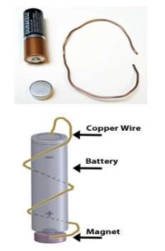
1.5 Volt Alkaline battery Neodymium magnet Copper wire Pliers Smart phone
1.4 Safety & Risk Assessment
The only hazard from this experiment is the possibility of being poked by the wire, having a slight burn on your fingers from the heated wires or to jam your fingers in between magnets. To prevent this from happening, there must be a lot of caution when handling the experiment, such as being alert where the wires are and not holding on to the wire for too long, as it may cause burn and also to keep all magnetic objects away from the neodymium magnet, as it is a very strong magnet and can jam your finger between objects or a sharp object.
2.0 Method
Experiment measuring how radius (r) and voltage (v) affects angular speed
- Place the neodymium magnet on a flat surface
 Place the negative (flat end) of the AAA battery onto the neodymium magnet.
- Use pliers to cut the wire to appropriate length.
- Mould and bend copper wire so that wire has a radius of 2cm from centre and make the two ends of the wire spiral down the battery and touch the magnet.
- The copper wire will move in a circular motion when the ends of the wire touch the magnet, record with smart phone.
- Review recording in slow motion and measure revolutions/minute.
- Repeat steps 2-6 for radii 3cm and 4cm.
- Repeat steps 2-7 for AA and D batteries.
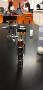
- Refer to Appendix 2 for picture of experiment.
3.0 Results and Analysis
|
Trial Number |
AAA Battery (1V) |
AA Battery (1.5V) |
D Battery (3V) |
|
Trial #1 (rads/s) |
4.7 |
5.6 |
10.1 |
|
Trial #2 (rads/s) |
4.6 |
5.3 |
10.1 |
|
Trial #3 (rads/s) |
4.8 |
5.2 |
9.8 |


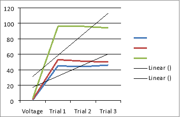
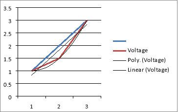
Figure 1 Figure 2
In figure 1, it shows that 1V (blue) and 1.5v (red) has a correlation with one another as a result of their respected lines almost being parallel. This is due to the two wires having almost the same voltage from the battery which would mean that the rpm would almost be the same.
3.1 Error Analysis
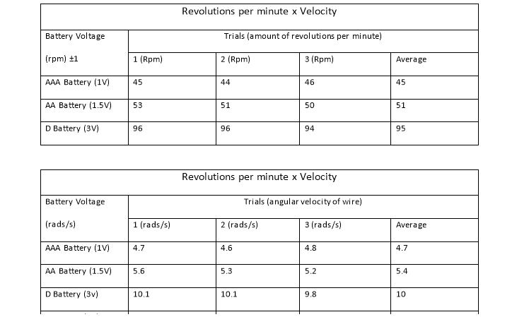
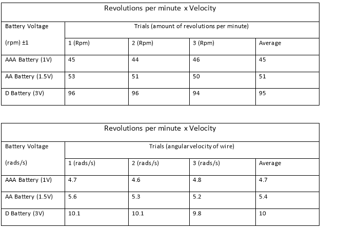
Table one show the result of the three different sized radii’s that was moulded to find the angular speed. A number of three trials were conducted to ensure that the results that were given were not abnormal and were accurate. Each trial went for 60 seconds each and the averages of the speed were calculated. In each trial, a margin of ±1 was used since the copper wire stopped halfway or not completing the rotation. As shown in table 1, it is clear that the bigger the radius of the wire, the slower the angular velocity. The difference is only slight because of the small difference in the radius of the wire.
4.0 Discussion
The results of the experiment support the hypothesis that, when the radius of wire was widened, the slower the revolutions per minute. But when it came to increasing the voltage of the battery, there was an increase in revolutions per minute. By using the same radii that were used in the previous experiment for the AAA battery, the speed is increased when the AA battery was used. Then the revolutions per minute were significantly increased when using the D battery due to the amount of voltage in the D battery.
From the data collected in table, angular velocity was able to be found using calculations shown in appendix 1. When the three batteries are compared, it is clear that as the battery voltage is increased, the faster the angular velocity. Even though increasing the radius of the wire affects the speed, it still supports the hypothesis that as the voltage is increased, the faster the angular velocity will be. As expected, the larger the amount of volts the battery discharges, the more current flows through the copper wire, causing it to have a higher revolution per minute rate. The greater the current flow the larger the magnetic field that is produced around the wire, and more force is produced to act upon making the wire spin.
The copper wire that was used was incredibly thin so there was not a lot of contact with the battery or the magnet. Since the wire is thin, there is a small path in which the current flows in which only give the electrons to flow in a straight line. If the wire was thicker and bigger in diameter, then there would be less resistance since the electrons would be able to flow freely. Since the batteries have a significantly low resistance, the electrons are free to flow easily through the thin copper wire. Therefore the factor of the resistance can be excluded when measuring the angular speed.
With the data collected, it was used to make a graph which showed the relationship between the volts of the battery and the angular speed. The vertical lines on the graph represent the margin error of ±1 since the wire did not complete the full revolution. Other possible errors that could have occurred while gathering this data was the rounding error, to minimize large numbers, two significant figures were used.
Copper wire loses conductivity after each consecutive trial without cutting the ends off. With the discovery of this possible error, cut the end bit of copper wire so that the conductivity would be the same each time which would make the results as accurate and precise as possible. Another possible source or error for this experiment is if the wire fell off the battery halfway through its rotations and/or if the ends of the copper wire lost direct contact to the magnet and slowed down during its rotations. These possible sources of error could be prevented by creating a slight dent on the battery to create a little hole for the wire to sit comfortably on and to create a solid spiral down the battery so that the ends don’t become loose and lose contact with the magnet. So that the results could be as precise as possible, because if the ends of the copper wire lose contact with the magnet, it loses the velocity and momentum and would slow down, and thus affects the rpm. Another possible source of error is drainage of the battery after consecutive trials causing less voltage to flow into the wire thus affecting its angular velocity, this could be prevented by using a power pack instead of battery.
5.0 Conclusion
In conclusion, the results that were gathered supported the hypothesis that even with a larger radius, when increasing the voltage of the battery, the angular speed is increased. As the results show that the D battery, although larger radius than the AA battery, still had twice the amount of revolutions per minute because it had twice the amount of voltage.
6.0 Appendix
Appendix 1
Using the formula for angular speed:


 Appendix 2
 Appendix 3

Appendix 4
Cite This Work
To export a reference to this article please select a referencing stye below:
Related Services
View all


DMCA / Removal Request
If you are the original writer of this essay and no longer wish to have your work published on UKEssays.com then please click the following link to email our support team:
Request essay removal