Systems Engineering: RTV Silicone Sealant Application System
| ✅ Paper Type: Free Essay | ✅ Subject: Engineering |
| ✅ Wordcount: 1873 words | ✅ Published: 31 Aug 2017 |
Abstract
As technology advances seemingly exponentially in the 21st century, the need for more and more complex systems grows too. Continuous improvement is key to a successful, growing business. This envelops everything within the organisation and engineered systems are no exception. Complex engineered systems require a level of control, this control is important for producing quality products and services. Considering advancing technology and continuous improvement, organisations need to explore ways in which the performance of engineered systems can be maximised. Multi-agent systems (MAS) are a relatively new theory which is put into practice when monolithic systems cannot solve the problem, so as systems become more and more complex, the need for MAS increase.
Glossary of Terms
FTT – defined as the percentage of engines that pass a process first time.
JPH – the number of engines which pass through a process per hour.
RTV – room temperature vulcanisation silicone sealant.
MAS – Multi-agent systems
1. Introduction
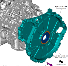
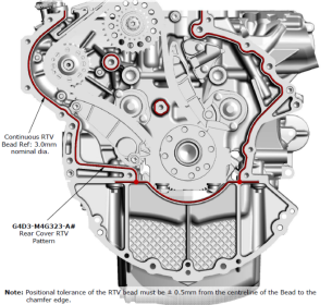 At the Engine Manufacturing Centre (EMC), Jaguar Land Rover (JLR) manufacture and assemble diesel and petrol engines. The author is a process engineer within the diesel assembly hall, whose main job role is to improve any assembly processes that negatively impact first time through (FTT) or jobs per hour (JPH). Currently, the issue that is causing the largest impact on said deliverables is the automatic application of RTV silicone sealant to the engine block to form a seal with the rear cover (Figure 1, below).
This automated process has an average FTT of 61% and a value of 59 JPH over the past thirty days. The target JPH value across the entire diesel assembly line is 68, which means this process is causing an average deficit of nine engines per hour causing considerable damage towards achieving production targets. The process itself is performed by two autonomous robots whereby one robot applies the sealant and the other robot holds the engine and moves it along a specified path. There are two HMIs present, one to program each robot. The robot holding the engine can be programmed with its position, its movement within the six degrees of freedom and its velocity. Whereas the only programmable functions are the start, end and speed and feed of the sealant.
2. Systems Engineering Life Cycle Stages
The role of systems engineering is to ensure the success of a system, judged by how well its requirements and development objectives are met, its operation in the field and the length of its useful operating life. Systems engineering aims to establish a technical approach that will aid the operational maintenance and the eventual upgrading of the system. A system life cycle is a term used to encapsulate the evolution of a new system, where it begins with a concept and grows through development into production, operation and lastly, destruction.
2.1 Concept Development
Where there is a desire for a new system, the concept development stage contains the planning and analysis required to affirm the need, the feasibility and the architecture for the new system to best satisfy the needs of the user.
There are four main objectives of the concept development stage:
- Decide whether there is a market and need for a technically and economically feasible system.
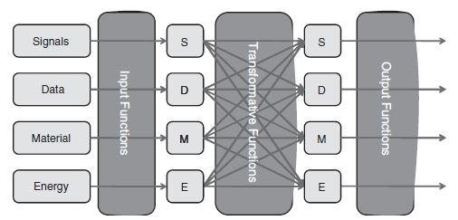
Design and confirm the system requirements after exploring different system concepts (see figure 3 below). This stage converts the system which has been derived from the needs analysis, into an engineering oriented view for the concept definition and development. When looking at performance requirements it is important to identify the major functions needed to complete the actions needed. In the case of this example, its functional elements should include, power robot, control movement, control speed, and apply RTV. To aid with this activity a systems engineer would use a function category versus functional media diagram (figure 4).
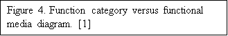
- Concept selection, agree on its characteristics and plan for the forthcoming stages of engineering, production and operation of the system. It answers the question “what are the key characteristics of a system concept that would achieve the most beneficial balance between capability, operational life, and cost?”[1].
- Develop and validate any technological developments required by the new system.
2.2 Engineering Development
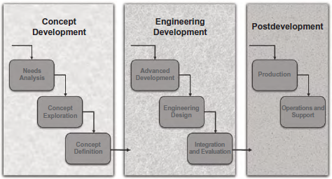
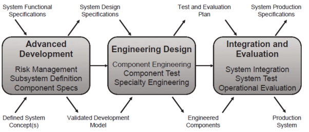 Figure 4 (below) shows three stages of engineering development. Firstly, the advanced development stage incorporates two important purposes. One being the identification and reduction of risks, the second being the development of system specifications. Secondly, the engineering design phase is considerably more detailed than any stages preceding it. Usually, this stage offers an opportunity for potential customers to get an early look at the product, who can, in turn, provide valuable feedback to the developers. Lastly, the integration and evaluation phase is where the new system is installed and subsequently checked to ensure that it meets customer requirements.
2.3 Post Development
Within the post-development phase there are two sub-phases; the production phase and the operations and support phase. The system is now being produced, for example, for a manufacturing environment. Occasionally there are unexpected issues that arise within the production of the system which requires a systems engineer to solve to prevent disruptions in the production schedule. Once the system is live, system support is critical. Maintenance personnel should be sufficient until more complex problems arise, where they need to call on the experience of systems engineers.

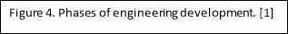
 3. Function Block Diagram

4. Control Architecture
4.1 Centralised Control
The centralised control system architecture has one component designated as the controller which is responsible for managing the execution of other components. The term architecture is used to suggest a focus on the relationship between the major structural elements in a system. This architecture falls into two classes depending on the execution of the controlled components, either sequentially or in parallel. These are the call-return model, only applicable in sequential systems, and the manager model, used in concurrent systems [3].
The main reasons to use centralised control architecture is that it is simple to conceive and due to its omniscience it can make optimal decisions which take all factors into account. However this architecture does have drawbacks, most notably the expense in which is required to create the control architecture, the control algorithm needs to be very complex. Furthermore, the degradation of any signal path can cripple the function of the entire system, so they can be fragile.
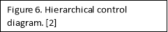
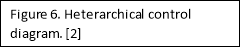
4.2 Hierarchical Control
Organised in a hierarchical tree, this control system decomposes the problem and allocates it to separate controllers which take control of a subset of the system functions. This can exist over a number of levels, meaning each function could be controlled individually. Optimal control is still possible within a hierarchical architecture as there is always a path to a top-level node; however, not all information can travel through every path. Commonly some filtering of data occurs between levels.
In contrast to centralised control, the control algorithm is much simpler due to decomposition. This means the time and cost of implementation are much lower. Between the different branches of the structure, there is a degree of independence, reducing the effect of system degradation. However, there is usually delay in the processing of each algorithm and in the feedback loop.
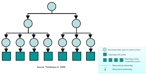
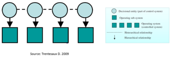
4.3 Heterarchical Control
Heterarchical control architecture is more robust than hierarchical control and is very flexible and extensible. Additional system functions, such as manufacturing processes and equipment, can be added with almost no added system control cost. However, heterarchical architecture lacks centralised visibility of the system as a whole which means planning can be sub-optimal; this control system is sometimes referred to as being short sighted. Though this does mean that short-term decision making is very good. [4]
4.4 RTV Robot Cell Control System
Centralised control is not suitable for the RTV robot cell system. The reason for this being the fact that it is too expensive to create and change. Additionally, the fault tolerance of the control system must be taken into account. A manufacturing line with such high demand for machine availability must not be crippled by the loss of just one signal.
The most suitable and, as it happens, the current control system architecture for this system would be hierarchical. The main downside to this architecture is its response time when there are lots and lots of levels. However, its strengths are combines the strengths of the other two control architectures discussed, albeit slightly diluted. Heterarchical control has strengths that would be fantastic for an automated cell in a manufacturing environment, but its weaknesses deem it unacceptable. If one could combine hierarchical and heterarchical architectures and take away the myopic nature of heterarchy, it could be a system which improves how automated cells are controlled.
5. Multi-Agent Systems
A multi-agent system is a system composed of multiple interacting intelligent agents. For problems that are too difficult or even impossible for an individual agent to solve, multi-agent systems can be used. Commonly thought of as being computerised, the agents within a multi-agent system could also be robots, humans, human teams or a combination of humans and robots. There are three different types of agents:
- Passive agents, agents without goals.
- Active agents, agents with simple goals.
- Cognitive agents, agents containing complex calculations.
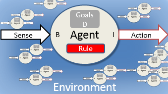
Agents can also be reactive or deliberative, this can be represented by the BDI model (figure 6- below).
BDI stands for Belief, Desire, Intention where belief is knowledge of the environment, desire is the need to satisfy an objective and intention is the ability to command action(s).
Deliberative agents extend the BDI model to include a symbolic model of the external environment- including data and relationships, memory, the ability to plan and the ability to choose between alternative actions.
One could make a case to incorporate multi-agent systems within an automated robot cell at the present time. There is a need for configurability, for example, when a new derivative of engine is introduced and the robot has to be programmed to function differently. The system will need robustness, so if one agent is lost it does not compromise the whole system. However using a hierarchical architecture provides a sufficient degree of configurability and robustness with less cost and complexity. Multi-agent systems provide dynamic task allocation rather than pre-planned schedules, for an automated robot cell this is not needed, automation needs efficiency in static conditions [5].
6. Conclusion
The automated RTV application robot cell is currently in the operational phase of the system lifecycle, it is in need of improvement however it is not the system that needs improving. The system works as it is meant to, however, it is the incorrect system that is in place which is causing the problems.
As automotive technology moves towards electrification and autonomous behaviour there will be a need to include more and more multi-agent systems within the vehicles themselves but also within manufacturing systems. There will be a need for greater flexibility, adaptability, reconfigurability and collaboration. Unfortunately, incorporating a multi-agent system in this instance would not have a positive impact on this system.
7. References
[1] Kossiakoff, Sweet, Seymour, Biemer. (2011). System Life Cycle. In: Sage, A. Systems Engineering Principles and Practice. 2nd ed. New Jersey: John Wiley & Sons, Inc.. 77.
[2] Lecture provided PowerPoint slides.
[3] Ian Sommerville. (2008). Centralized Control. Available: https://ifs.host.cs.st-andrews.ac.uk/Books/SE9/Web/Architecture/ArchPatterns/CentralControl.html. Last accessed 14/02/17.
[4] J.M. van de Mortel-Fronczak and J.E. Rooda. (1997). Heterarchical Control Systems for Production Cells. . 1 (1), 213-217.
[5] Various. (). Multi-agent system. Available: https://en.wikipedia.org/wiki/Multi-agent_system. Last accessed 20/02/17.
Cite This Work
To export a reference to this article please select a referencing stye below:
Related Services
View all


DMCA / Removal Request
If you are the original writer of this essay and no longer wish to have your work published on UKEssays.com then please click the following link to email our support team:
Request essay removal