Shaping, Joining and Surface Treatment Analysis
| ✅ Paper Type: Free Essay | ✅ Subject: Engineering |
| ✅ Wordcount: 4595 words | ✅ Published: 30 Aug 2017 |
MANUFACTURING PROCESS SELECTION
Introduction:
Process selection is a key responsible are in an industry where the specification from the customers is analysed and the suitable process for the desired product is isolated from the other manufacturing processes. This selection process in a company is very important as this determines the futuristic profit for the industry or the quality of the products that’s been produced from the plant.
In order to analyse the importance and economics of the various processes in manufacturing industry, most of the companies these days uses CES software which explains all the details a company should think about before starting the manufacturing process.
CES software details the important information on the history of the materials used for manufacturing process and suitable analysis based on their economics and environmental impact.
In this report, from CES mainly, the process universe is analysed based on the three process such as SHAPING, JOINING and SURFACE TREATMENT.
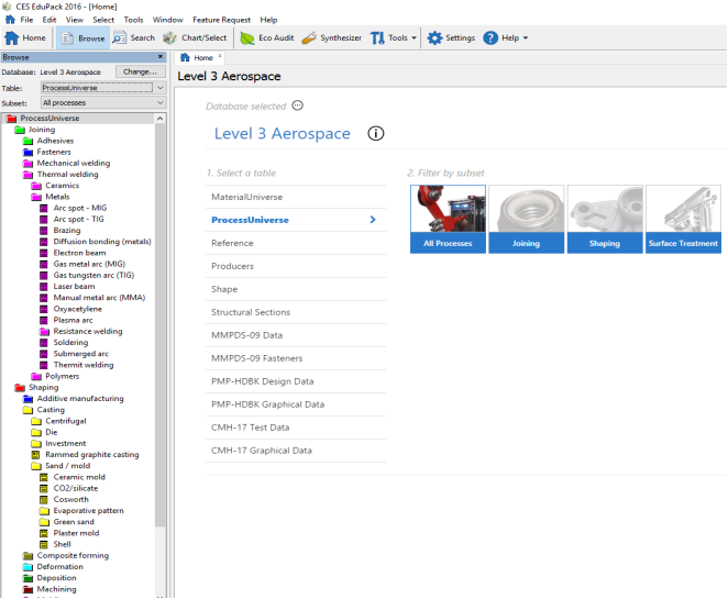
Figure 1 – CES database with process universe
Part 1
Manufacturing processes:
From the CES (Cambridge engineering selector) software, process universe database few of the processes were selected and analysed in detail using CES database and the sources outside CES in order to investigate these processes. Joining, Shaping and Surface treatment are the three manufacturing processes that were analysed in this report.
JOINING
Introduction:
This process describes the methods of joining parts together using various tools and methods in order to form certain assemblies which provides useful functions mechanically. At the very beginning joining process was very simple and basic like sewing using threads to stitch clothes, using paper clips, press studs and shoe laces. When it comes to fastening two objects or bodies together, all possible options should be considered in manufacturing processes in industries. Some of the basic classification of joining process are using Adhesives, Fasteners, Mechanical welding and Thermal welding. In industrial manufacturing process, joining process is widely divided into either permanent or non-permanent joining between two objects or surfaces.
One of the common process in joining metals is to fasten two parts or castings in order to merge the two surfaces of the objects. Metal objects like body armours were assembled using metal rivets. Before metal welding was introduced, riveting the metals bodies played an important role in joining manufacturing process.
BRAZING
Brazing is one of the basic methods used to join two pieces of metals together. The process starts with isolating the two parts of steel that are to be brazed and by cleaning the parts using wire wool or emery cloth would remove all the greases on the surfaces. A paste that is made from borax flux powder and water is applied along the joint. This prevents the process of oxidation on the surfaces as this inhibits the brazing procedure being successful. And when the compressor attached to the brazing torch is turned ON, this pressurises the gas and the air, and then the gas-air is turned ON slowly, feeding the gas through the small nozzle and this is then ignited at the end of nozzle using a match.
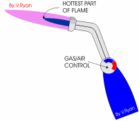
Figure 2 – Brazing torch
Once the torch is set and the hottest part of the brazing torch (tip of the blue part of the flame) is used to merge the two parts of the steel surfaces. Two pieces of the steel are placed on top of the rotating mount where it is easily accessed from all the directions. In order to lift the steel off the rotating mount, fire bricks are used and hence the heat produced can flow all over the surface rather than on one spot. The surfaces of the steel and the joining metal were given a gentle heat to raise the temperature in order to expand the metal edges and ready for brazing.
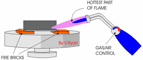
Figure 3 Brazing process setup
The flame is then moved forward and backward in order to focus the hottest part of the flame until the steel part becomes red hot. Then a brazing rod (copper – zinc alloy) is then pushed gently along the edges of the steel surfaces and when the temperature is right the rod will melt in the gaps to fill them and merge the metal and steel surfaces. The rod is fed until it runs along the joint is brazed in order to join them together. When this is complete, the steel is allowed to cool slowly by quenching in water because cooling the metal quickly may break or crack the joint or it may become distorted.
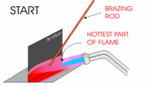
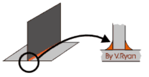
Figure4heatingprocessFigure 5 Brazed material
Types of materials
Brazing is the process which is widely used to heat exchangers, bicycle frames, boilers, copper pipes, and pipework fittings and to repair castings and assemble machine parts. Metals, Ceramics and dissimilar materials are normally brazed using this process in industries.
A variety of alloys are used in brazing the materials by using the alloys for filtering. Some of the materials that are used as common filters are,
- Silver
- Copper
- Nickel alloy
- Gold silver
- Copper silver
- Aluminium silicon
- Copper zinc
Most commonly, the brazing materials come as in the form of rod, powder, ribbon, paste, wire and preforms such as stamped washers.
Characteristics of the components
Brazing process will be able to fit within the sectional thickness of range from 0.1mm to 30mm. some might cover the points beyond this range, however, this may affect the increase in cost and time for the process in order to take place. The minimum section thickness is always determined by the process and the materials used within the certain manufacturing companies.
Nominal tolerance for the brazing process is in the range from 0.05mm to 0.5mm and the resulting processed materials may be outside the tolerance range but this might affect the time for processing and the cost for the manufacturers. Some accuracy like precision or the surface roughness can be determined by the nature of the process.
Economics of the process
Brazing can be done manually and by using automated machines which is using the furnace. Generally manual process takes time and using the torch to braze a material requires certain skill level. On the other hand, automated furnace brazing requires no skill and no labour costs. Therefore, this brazing process is cheap and tools are fairly cost worthy as well and it is very economical for small runs in certain companies. Yet this process allows high production rates when the whole process is automated at large or industrial scale.
SHAPING
Introduction:
Shaping is a process that was developed over time from ancient times when machines were involved in manufacturing processes. However, these types of shaping machines are not widely used in the current manufacturing industries although they had very substantial development. This process was used to cut metal tools and other parts in early days on the flat surfaces, yet these were used as a drawback in this times. Shaping produces the flat surfaces by moving a single point in a reciprocating or zigzag motion. The forward stroke is the cutting edge motion and the reverse motion is finished with high velocity motion in order to include the sideways feeding motion.
CERAMIC MOLD CASTING
Ceramic mold casting is a process which uses high temperatures in order to cast certain parts of machines or even tools, used in various machineries. This process is also like plaster mold casting but instead of using plaster to create metal parts or castings, ceramic casting uses refractory mold materials for casting. In an industrial level the parts used as cutting machinery or metal molds die for metalworking or even the metal impellers can also be manufactured using this type of casting processes.
Nature of the process
This process kicks off with preparing the platform for pouring the material for molding. A mixture of fine grain ZIRCON (ZrSiO4), aluminium oxide, fused silica, bonding agents and water which creates a ceramic slurry solution for the mold to be dipped in or immersed in this solution.
When the mold is set in the slurry solution in the platform, the pattern is then removed and the casted mold is then left off to dry. Then using high flamed torch, the mold is then fired in order to melt or heat off the excess cast around the mold.
This firing the mold process will also burn off any unwanted waste materials on the mold and make it rigid and hardened for the future polishing process. In order to add more strength and rigidity the mold is then baked in an oven over a certain time period or even heated in the furnace.
The firing process leaves the mold with few cracks and lines which then adding the mold extra permeability and collapsibility for the metal processing that comes later in the industrial scale manufacturing process.

Figure 6 ceramic casting process
Once the mold was prepared the two halves were then joined together for assembly and be ready to pour the casting or molten material into the molds. The two halves also called as cope and drag section are then backed up with the fireclay materials for additional molding strength. Often in these types of processes in manufacturing industry, the ceramic mold is preheated in the oven in order to pour the molten metal into the cast.

The metal casting is poured and let to solidify, in ceramic molding process in industries, like in other expandable mold processes, the ceramic mold is destroyed in the removal process of the metal casting. The ceramic mold itself can be a shell, for small manufacture processing components, or a box less block mold, for large industrial components, or even a composite mold combines both the shell which then backed up with a cheaper material like the large components that are produced in large quantities.
The insulating nature of the ceramic mold prevents the molds from decaying or decomposing and prolongs the lifespan of the cycle time however the manufacturing ceramic casting process lends itself to mechanization and rapid output of molds.
Types of materials
Ceramic casting process plays a vital role in casting metal components such as tools used for forging and extrusion and even die casting. This process also used in the glass production. Some of the materials that has been processed in this way are,
- Aerospace parts and components
- Marine fitting tools
- Propellers for ships and small turbines
- Complex gearing parts
- Pumps and valves
- Pipes and precision machinery parts
- Impellers
Characteristics of the components
Mass range for this casting process is from 0.2kg to 50kg of weight and this is determined by the capacity of the casting mold or the caster, the press that the mold undergoes and the machine tools, etc. this can also often be extruded or extended with the help of additional process of fabricating. 1.5mm to 999mm is the range of the sectional thickness of the materials or the casting mold that is being used in the casting process in the industrial scale of manufacturing process.
This is determined by the fluid flow in castings or the plastic constraints used in the molding process or the melt flow length in injection molding, etc. this process can generally be further outside the range resulting increase in cost for material and time for the process to take place in an industry.
The range of tolerance for this casting process is from 0.38mm to 0.8mm in length or measurement as the achiever tolerance can be refined by secondary machining operations such as precision grinding and polishing in order to remove the extra unwanted materials and keep the accuracy nearly to 100%. 1.6µm to 3.2µm is the range of roughness for this process as this is controlled by smoothness of the molds or casting surfaces.
Economics of the process
Ceramic mold casting is relatively expensive. The tools costs cover a range from small, simple to large, complex molding materials and they vary in size shape and structure. To be able to cast parts at higher accuracy elements eliminates the need for machinery which reduces the cost for automated process but this casting is mainly monitored with watchful eyes and that increases labouring costs and training men in different aspects of skills development.
The long preparation time taken in molds increasing makes the manufacturing production rates at very low intervals and increasing demands for new molds with certain improvements.
SURFACE TREATMENT
Introduction:
Surface treatment can be used in various ways in order to clean or polish the surface of the materials using various techniques. This includes polishing or grinding the metals as well as smoothening the outer surface of the body of the materials used in manufacturing. Surface treatment of the metals involves the creation of a barrier that can protect the metal parts like a wall around the body in order to prevent corrosion or other chemical or environmental damages.
The surface layer forming on a metal that is scheduled for chemical coating is created due to a chemical reaction which is non electrolytic in nature in order to achieve great and precision results in industrial manufacturing process.
GRINDING
Grinding is a slow process that polishes the surface of a material yet not removing a large sized part from the object or cutting the big edge off the material. In the past, this process was only used to machining processes or final dimension accuracy treatments by finishing the surface of the materials. But the developed or renowned new processes are changing the thought process that’s been used over the years of time.
Utilizing new grinding techniques, incredible material removal rate has increased up to 300mm3/smm, which is equal to 28 cubic inches per minute. This process allows the tough edges in aerospace markets, where the materials are made up of tough alloy or nickel to be removed and polished.
Nature of the process
Grinding process normally associated with the tools that’s been used in the process of grinding. A grinding tool is used to grind down or polish metals or glass surfaces. Grinder is more like a sander which uses the abrasive surface of the grinder to remove the minute particles on the materials.
Grinding process actually sharpens the wheel that is attached to the grinder by braking those particles and creating new grinding points in the wheel. A grinding wheel is made from several chemical and mineral ingredients, this composition of particles may vary according to the purpose of the wheel that is used in the industry like whether to grind metals or polish ceramic glasses.
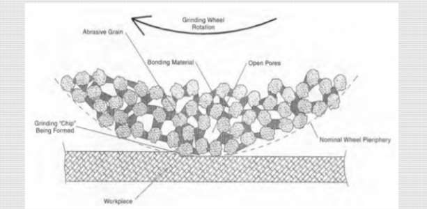
Figure 7 bonding particles in grinding wheel making process
For metals they use the grinding wheel made from aluminium oxide granules to create that very abrasive surface of the wheel. For non-metals components, silicon based particles are used in the making of surface of the grinding wheels.
These particles are added in weighed scales and by using resin bonding agents these particles are then bonded in shape to form the grinding wheels which are then used in the grinders for appropriate uses.
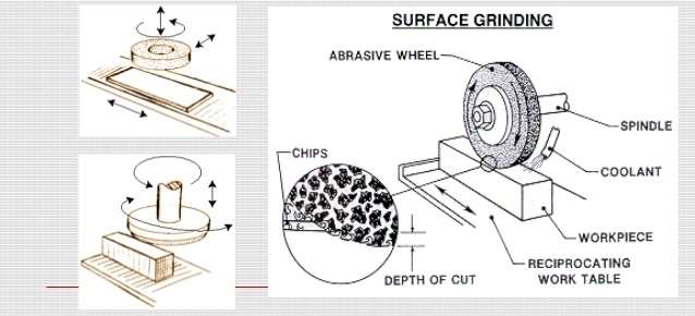
Figure 8 grinding process with grinding wheels
Types of materials
Grinding also used to cut hardened steel, which produces very smooth surfaces. Surface pressure is minimum in grinding, which is suitable for light or small works that will spring away from the cutting tool in the other machining processes. It can be classified into rough and precision grinding. Rough grinding eliminates the primary layer of the materials that are with the huge or big part of the edges and extra addition of materials.
This prepares the materials for further grinding with precision and increased accuracy. Surface grinding uses a rotating abrasive wheel to remove material which creates a flat surface. Pistons, pins, gears and shafts are some of the materials prepared by this grinding process. Rivets, valves and pipe fittings and lenses and mirrors for precision optical equipment.
Characteristics of the components
Surface smoothness of the materials used under grinding process achieve the high precision. The maximum temperature attained during this process is ranges from 70 to 370 C, this is due to the interaction between the grinding wheel and the material that is being grinded in the process. Unfortunately, the grinding process does not even out all parts of the material which indicates whether the treatment reaches its maximum precision level. At this process the curved surface coverage is very poor.
Economics of the process
The tools used for grinding process are fairly cheap and affordable. This is for manual polishing tools only with the approximate range of price from capital cost being £90 to £1000 and tooling cost ranges from £8 to £200 however this results in the production rates being very low as this is a manual process. Automatic machining processes can be expensive for both capital (ranges from £1800 to £1,000,000) and tooling machines (ranges from £900 to £10,000) but this shows higher production rates in manufacturing.
PART 2
In depth case study analysis
Using CES software the following charts are drawn and one of the given case study is analysed with the help of CES software.
 Manifold Jacket
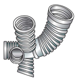
Figure 9 Manifold Jacket – hollow 3D model
The part shown above is called manifold jacket, is used in aerospace shuttles and vehicles. This component is made from nickel and it weighs about 7 Kg as this is a large 3D hollow dimensioned component it has a thickness of 2 – 5 mm with a precision tolerance of 0.1 mm. In this process of manufacturing case study, we only going to manufacture 10 units as this limited usage in the industry.
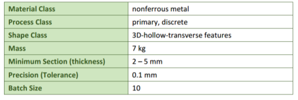
Table 1 design requirements – Manifold Jacket
Material class selection
- Mass range Vs Material class
The required material for this manifold jacket comes from a non-ferrous alloy. The chart below explains the class of materials fall in the range from 5 to 10 Kg of mass range of the chosen material (Non-ferrous alloy). From CES software the chart was created by labelling Y-Axis (Mass range – Kg) and X-Axis (Material class – Non-ferrous alloys). Then certain range as given above (5 to 10 Kg) was isolated using the box tool and the processes that satisfies the approximate length and mass are then labelled in the chart.
The box in the chart isolates the processes which can shape these alloys and can handle the desired mass range of 5 – 10 Kg. Mass range was the Y axis and it was selected from the Process universe > Shaping > Mass range from the chart dialog box. Material class on the X-axis was chose from the advanced features and under Tree > Material universe > Metals > Non-ferrous alloys.
In order to choose the limit to isolate the required process selection, a box was drawn in the chart body and right clicked on to Properties > Specified range 5 – 10 Kg in under the mass range sub heading. Then the chart was then zoomed in according to label the processes. By clicking and dragging on each of the coloured lines the desired processes can be identified.
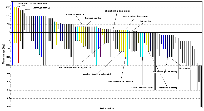
Chart 1 mass range VS nonferrous alloy
- Thickness Vs Shape class
The chart below shows the relationship between the range of section thickness of the chosen materials and to see which processes can produce a 3D hollow shape of the material with transverse features.
The chart was plotted by choosing range of thickness for Y-axis and hollow 3D with transverse features on the X-axis. By selecting Chart > Y axis > Range of section Thickness was selected in order to plot the graph and X axis > Advanced > Tree > Shape > 3D shaping > Transverse features.
A box was marked in the chart by selecting box tool in order to isolate the processes that are capable of making that desired 3D hollow feature with the transverse feature as well.
This box was in the range of section thickness from 2 mm to 5 mm. the processes outside the desired range are in different colour since these processes failed to produce the desired results within the certain limitation and ranges specified by the manufacturing company or industry.
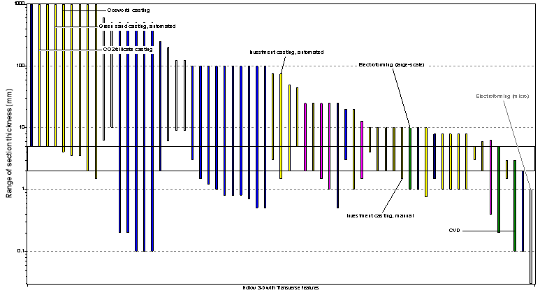
Chart 2 range of section thickness VS hollow 3D with transverse features
- Tolerance Vs Primary shaping process
The process selection chart below refers to the interaction between the tolerance that the selection process can have and the trueness of the primary shaping process that is responsible for the formation of this manifold jacket.
This chart was plotted using CES by selecting Chart from the process universe and under Shaping process > Y axis > Tolerance (mm) and on the other hand for X axis > Primary shaping process was selected on the same dialog box as both are under shaping process sub heading.
Few processes that can be used to make this product within the limited tolerance and accuracy of the ranges are then isolated from the chart using a box tool and drawing the box for only the processes that can satisfy which means whatever lies on the box after TRUE phase and the applicable tolerance was specified.
The tolerance level for these processes ranges from 0.1 mm and whatever above this tolerance and belong to the true phase then these processes can be used to manufacture the desired product with the possible tolerance output.
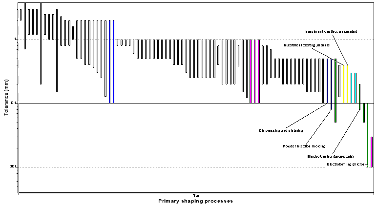
Chart 3 tolerance VS primary shaping processes
- Economics Vs Discrete
The chart below was plotted against the Economics of the batch size of 10 units that’s been produced from the manufacturing processes. This chart explains the cost for the manufacturing process and see how much this process cost for the company would in order to produce 10 units of the desired products.
Using the box tool from CES, 10-unit scale was isolated from the chart and the processes which can produce the certain amount of products are labelled outside the chart.
Economics batch size in units is plotted in Y axis by selecting form Chart > Y axis > Economics batch size and for the X axis from the shaping process universe > X axis > Discrete was selected. Only the true section of the chart which can produce the desired materials can be isolated and units of 10 were boxed in order to see which processes can achieve this manufacturing process.

Table 2 processes of the manifold jacket
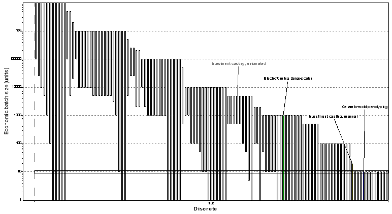
Chart 4 economics of the batch size VS discrete
Methodology and conclusion
Before even the part was made, it was important to meet the customer requirements and produce a report on how the production is going to take place and how this might satisfy the customers’ needs in order to make the production more efficient and effective.
To make Manifold jackets it seems that Electroforming and investment casting are the right processes with the suitable economics and even for small number of units the casting works out just fine.
These types of products are used in small number of units such as in aerospace vehicles and shuttles therefore it doesn’t have to be produced in vast quantities. But in order to produce in bulk operations this process could cost very high and more expensive when it comes to the process being automated as the machines for these types of processes could cost effective and hard to maintain.
If the process is manual this could cost much worthy for the company as in training staffs and more labour could result in expensive treatments.
When it comes to large scale production of the desired products Electroforming is the only solution and for the manual process side, Investment casting emerged as a suitable solution.
However, before any of these decisions been made, a brief analysis of the investment and profit report such as a cost analysis report is advisable in order to proceed with the project in future.
And the analysis from the labours also advised in order to maintain a constant and continuous production in line in the factory in near future.
PART 3
Environmental Impact of Process Selection
ECO AUDIT TOOL
To evaluate the environmental impact of the designed product and to analyse the ways to reduce this effect on the environment, ECO-AUDIT tool in CES software is used. This concept is achieved by focusing on energy usage and CO2 footprint of the materials used in the process of manufacturing. The product design forms the objective for the methods used and this resulted from a class of material selection.
The objective is dependent on both product application and dominant phase, when the use phase is dominant the objective for a car would be minimize mass, whereas for a boiler, it would be to minimise thermal loss from the manufacturing process.
Eco audit tool helps us to perform small or large quick audit before even we begin the report. This part of the CES software helps you to track and focus on the environmental requirements and simple and quantitative reports are being produced in order to demonstrate the compliance.
This way it saves money by identifying the early stage corrections and before even the resources were submitted.
Methodology of ECO Audit tool
The methodology system in ECO audit helps us to easily interact with the tools and get some environmental impact of the manufacturing processes or the materials used for the manufacturing process quickly and effectively.
This way you can track the product sustainability, comply with the customers target or the company’s and even help us with more ideas in order to improve the design for manufacturing. If the goal is to minimise the environmental impact of the processes performed in the environment we need a quick and effective means of valuable report in order to judge the performance or the quantitative assessment.
The whole processes in the ECO audit methodology can be summarised by the following image which clearly explains the steps and analysis of the process.
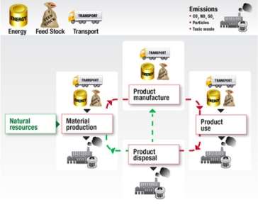
Figure 10 methodology of ECO Audit process
Advantages
It helps us to make quick and early decisions based on the corrections and solutions given by the eco audit tool and this saves the company a plenty of time and money by identifying the mistakes in early designs and early stages.
In order to use this software, the company or the industrial personnel does not need a specific knowledge therefore this product can be used across the company by anyone making this software more accessible for everyone and engineers can be supported by this software and take advantage by using this to make changes in their environmental audition report.
It also helps the company to demonstrate the progression towards sustainability goals that’s been set or achieved for the customers and some of the investors from other companies and sectors through benchmarks and some other better quantitative measures made.
Case study – Glass bottle
We are trying to find out all the information regarding this product. For this we can use ECO audit tool which can tell us about the life cycle of this product, transport and uses for this product. This tool also clarifies the information for the energy consumed by this product and the CO2 emission for this product.
We now analyse the design and the materials used in order to form this bottle including the cap of the bottle and also analyse where the bottle actually transported from and the net weight of the product or the balance weight that this product can maintain.
Product manufacture
The name of the product is Glass bottle with the aluminium cap that can be filled with 1 litre of mineral water which could also mean that the net weight of the materials and the whole product is 1Kg.
Table 3 materials in manufacturing the product
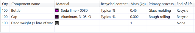
All the materials that the bottle was made up of can be recycled which indicates that the whole product is very Eco friendly and very beneficial to the environment.
Transport
The bottle itself was manufactured in France and it has been transported 550 km to UK with the help of
Cite This Work
To export a reference to this article please select a referencing stye below:
Related Services
View all


DMCA / Removal Request
If you are the original writer of this essay and no longer wish to have your work published on UKEssays.com then please click the following link to email our support team:
Request essay removal