Reconfiguration of 11KV Feeder
| ✅ Paper Type: Free Essay | ✅ Subject: Engineering |
| ✅ Wordcount: 751 words | ✅ Published: 31 Aug 2017 |
- Introduction
CE 2.1
I did this project as a graduate Electrical Engineering while pursuing my Bachelor of Engineering in the field of Electrical Engineering from Balochistan University of Engineering and Technology, Balochistan.
I wanted to conduct a project that would be challenging and would involve how to improve the existing power grid by helping the current or load at a given time. I wanted to create a system by improving the power factor or changing the conductor size or substituting the cables with conductors. I was able to improve my written and oral presentation skills as well as my interpersonal skills by the successful completion of this project.
- Background
CE 2.2
For this project as an undergraduate student in electrical engineering, I wanted to start working on a project that would be challenging. I wanted to learn about the different and commonly used electrical/electronic components, the working mechanism and the implementation in a common every-day system. Feeder configuration is a very important step to enhance the quality and reliability of a distribution system. During my studies, I had learned that traditionally, in Pakistan, the feeder configuration is done by opening/closing or tie & sectionalizing the switches in order to alter network map and thus the flow of power from substation to customers.

I had studied during my bachelors that the reason Feeder configuration is done is to reduce system power loss and also for load balancing. As the loading conditions change, it is important to reconfigure it to reduce power losses in the network. And it is due to this reason that I selected the “Reconfiguration of 11KV Feeder” for my project.
CE 2.3
The objective of my project is to design a system to reconfigure the network for loss reduction for 11KV feeder. Or the reconfiguration of the distribution network under normal operation to reduce active losses and to balance loads in the system.
CE 2.4


CE 2.5
- I first had to conduct a detailed literature review to find the best applicable approach to this system for reconfiguration.
- I decided to use Branch exchange and Loop cutting methods along with a theoretical Heurestic approach to achieve my objectives.
- I used the computer software for “ELR” to analyse the feeder and to calculate the results.
- I initially, used an existing configuration based on actual data to calculate the current Energy Loss Reduction (ELR)
- I then tabulated all the results and obtained a schematic diagram to show my results.
- I completed the project within the time frame specified by the university.
- I presented my findings to my supervisor.
- Personal Engineering Activity
CE 2.6
I approached a senior professor with an idea of conducting a project about the power grid. Along with my group members, I had a lot of brainstorming sessions and review meetings with my project supervisor to select a suitable topic. I suggested that I work on a project that was concerned with restructuring the power grid to minimize distribution losses and we suggested that we select a suitable location for this project to be carried out and thus the topic “Reconfiguration of 11KV feeder” came in to being and the supervisor agreed to this and asked us to begin working on this by first conducting a literature review on all the components we would require and the working of this project and to start working on this project.
CE 2.7
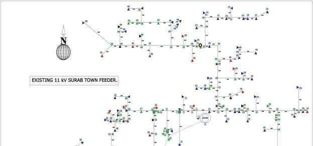
- I decided to select a Surab Town feeder of 11KV which starts from the 132KV Pakistan Railway Grid Station. I found that this grid has two transformers connected in parallel having a capacity of 10/13MVA each and 132/11KV. This particular feeder provided power of mixed loads to residential, commercial, agricultural and gas power plants. I carried out the Physical Survey of the existing 11KV Surab Town Feeder and plotted a Single line diagram of existing Surab town feeder.
- I calculated the energy losses and voltage drop of existing distribution system keeping in view the QESCO requirements. The length of feeder is 42.62km with annual energy loss 457898.1kWH and maximum percentage voltage drop is 6.5%, which is beyond the specified limit of QESCO i.e. 5.0% and is not acceptable as shown in the table below.
|
Month |
Max Hour KWH Reading in Year-3 (KWH) |
Units Sent in Year-3 (KWH) |
Units Sold in Year-3 (KWH) |
Losses |
||
|
KWH |
% |
|||||
|
January |
0920108 |
0922574 |
1954326 |
1020746 |
933580 |
47.8 |
|
February |
1809123 |
1811499 |
1504110 |
785804 |
719490 |
47.8 |
|
March |
2577218 |
2580502 |
1233398 |
1324005 |
-90607 |
-7.3 |
|
April |
2944920 |
2946703 |
1695002 |
1472175 |
223911 |
13.2 |
|
May |
4197868 |
4199507 |
1758256 |
1693000 |
65256 |
3.7 |
|
June |
4483081 |
4485732 |
1472868 |
1392621 |
84892 |
5.8 |
|
July |
5663010 |
5665217 |
1452128 |
1146852 |
303276 |
21.0 |
|
August |
6179532 |
6174379 |
1272432 |
1263513 |
8919 |
0.7 |
|
September |
72162 |
76150 |
1636414 |
5107276 |
129138 |
7.9 |
|
October |
1747258 |
172496 |
2070467 |
1654039 |
418057 |
20.2 |
|
November |
4868322 |
4873227 |
2704009 |
1584898 |
1119111 |
41.4 |
|
December |
6046270 |
602780 |
3086286 |
1626763 |
1459523 |
47.3 |
- I used the following simple algorithm for the algorithm:
Start with an existing configuration.
Read Input data..Run ELR program..Display results..Compare KWH losses,
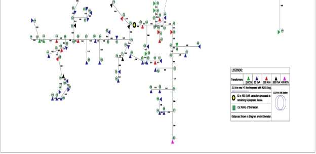
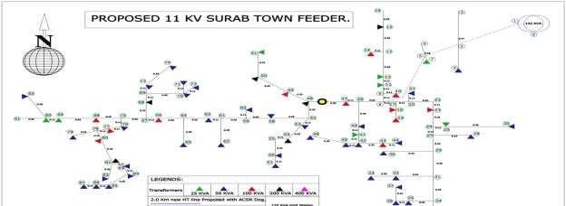
If KWH loss CE 2.8 Load in Amp.=395 Amp @ 5% for 5 years Bus Voltage=11KV Feeder load factor=6.29% Existing power factor=0.78% Proposed power factor=0.79% Capacitor installed=2Nos. This configuration has reduced the line losses too as evident from the load flow analysis. The details are feeder given below. Power T/F # ΙΙ Feeder code 020201 Power T/F capacity 10/13 MVA Number of node 92 Number of transformers 66 Number dog conductor 18 Number rabbit conductor 73 Total length of line 18.42 KM Total KVAS 5350 KVA Load in Amp= 395A@5%for 5 years Bus Voltage = 11KV Feeder load factor= 6.29% Existing power factor = 0.78% Proposed power factor = 0.95% (Improved Due to capacitor Placement) CE 2.9 I conducted this project successfully and found that the ELR program could be used sappropriately and properly to find the optimal configuration of 11KV feeder, demonstrating the feasibility of such an approach for the solution of this problem. However, refinements to the algorithm may be necessary in order to achieve satisfactory performance on large, real-world systems consisting of thousands of buses. The following were my results: CE 2.10 My contribution during this project was: CE 2.9 I successfully completed the project titled “Reconfiguration of a 11KV Feeder” along with my team members. I learned how to reconfigure a 11KV feeder and about the different approaches by execution of the ELR program I learned how to gather Grid data for realistic approaches to improve loading. By the successful completion of this project, I was able to improve my written, oral and interpersonal skills. I was also able to improve my team work. The main objective of this research is to develop methodology and guide lines for distribution engineers to show that by reducing the energy losses of distribution system, available capacity of the system may be conserved without putting up additional capacity. A generalized computer program is used to evaluate any given HT/LT system and propose capacitor banks at different points, different conductor sizes in different portions of system. This results in improving the stability as well as energy handling capacity of the system at minimum cost.

Cite This Work
To export a reference to this article please select a referencing stye below:
Related Services
View all


DMCA / Removal Request
If you are the original writer of this essay and no longer wish to have your work published on UKEssays.com then please click the following link to email our support team:
Request essay removal