Pv Value in a Seal – Questions and Answers
| ✅ Paper Type: Free Essay | ✅ Subject: Engineering |
| ✅ Wordcount: 271 words | ✅ Published: 30 Aug 2017 |
Question 1 (4 marks)
List 4 important parameters (not the equation parameters) that are determined by the Pv value in a seal.
|
|
Assessor Feedback |
Question 2 (4 marks)
The contact property of the interface is influenced by which component in a seal unit? What is the need for seal balance?
|
|
Assessor Feedback |
Question 3(8 marks)
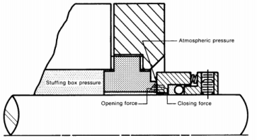
Given the following data, calculate the face area, spring pressure and balance ratios (external and internal) of a seal, for both externally acting and internally acting pressures. Is this Balanced or Unbalanced and why?
- Seal face contact outer diameter, D = 61.8 mm
- Effective seal balance diameter, B = 52.6 mm
- Deal face contact inner diameter, d = 49.2 mm
- Spring force at working length, F =188 N
|
Calculate the face area of the seal: Α=Ï€(D_0^2-D_1^2 )/4 Α=Ï€(ã€-68.2ã€-^2-ã€-49.2ã€-^2 )/4 =1098.46 ã€-mmã€-^2 A=0.001098ã€- mã€-^2 Calculate the spring pressure: P_sp=F_sp/A =188/0.00109846 =171148.7 ã€-N/ã€-_(m^2 ) =P_sp 0.17115 MPa Calculate the balance ratio for the external loading: B=(D_0^2-D_b^2)/(D_0^2-D_t^2 ) Α=(ã€-61.8ã€-^2-ã€-52.6ã€-^2)/(ã€-61.8ã€-^2-ã€-49.2ã€-^2 ) =1052.48/1398.6 B=0.753 (B<1;Balanced) Calculate the balance ration for the internal loading B=(D_b^2-D_t^2)/(D_0^2-D_t^2 ) Α=(ã€-52.6ã€-^2-ã€-49.2ã€-^2)/(ã€-61.8ã€-^2-ã€-49.2ã€-^2 ) =346.12/1398.6 B=0.25 (B<1;Balanced) |
|
Assessor Feedback |
Question 4 (4 marks)
From the following single mechanical seals, identify the 7 sealing components and other mechanical components, briefly describing their functions?
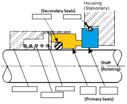
2)Primary Sealing Ring. 3) O-ring. 4) O-Ring. 5) Disc. 6) Spring. 7) Retainer.
|
|
Assessor Feedback |
Question 5 (4 marks)
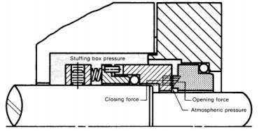
What difference do you notice between the two mechanical seals shown below. Name them and describe their application.
|
|
Assessor Feedback |
Question 6 (4 marks)
Name the primary sealing elements in a single mechanical seal.
|
1) Primary sealing surfaces. 2) Secondary sealing surfaces. 3) a means of actuation. 4) a means of drive. |
|
Assessor Feedback |
Question 7 (4 marks)
While it’s accepted that solid alumina ceramic seal rings will be considerably more expensive than ceramic coated steel rings, why should they be the preferred choice between the two types of seal ring?
|
When handling corrosive fluids at moderate pressures and velocities: alumina ceramics may be employed as thin coatings or solid rings (preferred!!) For highly corrosive fluids: high purity ceramic alumina can be used. Alumina ceramics have: Relatively low tensile strength Poor resistance to thermal shock Low thermal conductivity High elasticity modulus |
|
Assessor Feedback |
Question 8 (4 marks)
Which dynamic secondary sealing element is the preferred type to handle axial movement? Give reasons for your answer. What type of damage does a wedge type secondary seal do to pump shafts/sleeves? Explain how this mechanism works.
|
|
Assessor Feedback |
Question 9 (4 marks)
What is the distinct advantage offered by a bellows seal? How can the design be improved to accommodate higher pressures? Which bellows material offers the best corrosion resistance?
|
One of the most frequent and serious problems valves face is gland leakage, results in wasted and increased plant downtime. Apart from the high cost of energy losses, Gland leakages can also cause serious environmental, ecological and health hazards to plant workers and personnel. Leakage of sensitive material can also constitute to a fire hazard, explosion, or damage to equipment by corrosive material. Air entering the pipeline could produce inflammable explosive or poisonous mixtures. Gland packed valves often demand continual maintenance in accessibility creating particular difficulties. The bellows comply to conditions at high temperatures and are capable of withstanding over 10,000 cycles without failure. Bellow Seals are also known as ‘Zero Leak Valves’ or ‘Emission Free Valves’ The multi-ply bellow design is preferred for handling higher pressure fluids (generally two or three plies of the metal wall). A two ply bellow can increase its pressure rating by 80% to 100% as compared to a single ply bellow of the same thickness. Alternatively, if a single ply bellow of a thickness equivalent to a pressure rating of a two ply bellow is used, the stroke length is reduced. Thus, a multi-ply bellow design offers a distinct advantage over a single ply bellow. The stainless steel bellow material AISI 316Ti which contains Titanium to withstand high temperatures. Alternatively, Inconel 600 or Inconel 625 improve fatigue strength and corrosion resistance as compared with stainless steel bellows. Similarly, Hastalloy C-276 offers greater corrosion resistance and fatigue strength than Inconel 625. Fatigue resistance can be improved by using a multiply bellows system and reducing the stroke length; this can significantly increase the bellow service life. |
|
Assessor Feedback |
Question 10 (6 marks)
Do a comparative analysis of inboard and outboard mounting of seals.
|
Inside-mounted seal is the most common in the industry and the most energy-efficient when compared with other sealing methods, such as packing and seal less equipment. They are used in all industries with respect to fluid types and the seals’ property ranges, pressure speed, diameter and temperature. 
Inside seals are mounted within the equipment seal chamber the advantages of this design include: The seal can be cooled by the pumped fluid in an enlarged dead-ended chamber, by a product bypass flush or by a clean external flush. Depending on the seal chamber design, the rotary action of the seal assembly may help keep debris away from the seal faces. With proper hydraulic balancing, the product pressure helps keep the seal faces closed. Catastrophic leakage is usually avoided during seal failure. Leakage can be restricted by the stationary elements in the gland. Inside seals are available in many materials and designs. Environmental controls are easily included in the design. Centrifugal forces tend to reduce leakage.
The seal can often be backed-off for cleaning. |
|
Assessor Feedback |
Question 11 (8 marks)
Explain the difference between static and dynamic seals?
|
0-rings are used for effective sealing in applications. Mostly, they are used to help repair or correct any manufacturing or installation defects seen in glands. 0-rings can be used in static as well as dynamic applications. The make of both these 0-rings will be different owing to the difference in application requirements. The following are some major differences between static and dynamic 0-rings: The material used to manufacture dynamic 0-rings should be tougher than that used to manufacture static 0-rings.This is because the dynamic 0-ring will have to undergo movement while the application is functioning. In dynamic applications, the surface finish and material of the gland should be such that it doesn’t abrade the 0-ring during movement otherwise, the 0-ring could tear this is irrelevant in static applications, where the 0-ring doesn’t move. 0-rings used in dynamic applications are likely to wear at a faster rate as compared to static 0-rings. This is because dynamic 0-rings are constantly moving. Hence, the interval of maintenance procedures for dynamic 0-rings should be shorter than that of static 0-rings. •All 0-rings should be properly lubricated at all times. •Dyna mic 0-rings require more lubrication than static ones. Depending on the application, static or dynamic seals will be used. O-rings are useful in a varied number of industries and applications. They are effective across a wide range of temperatures and pressures. However, using the right 0-ring for each application will help you increase the reliability and service life of the 0-ring. You can consult with your 0-ring manufacturer on the best fit for your application |
|
Assessor Feedback |
Question 12 (4 marks)
Why are mechanical seals preloaded? Name four of the most common types of preloading for pump seals.
|
Depending on the application it may be necessary to have either a positive or a negative operational clearance in the bearing arrangement. In the majority of applications, the operational clearance should be positive, i.e. when in operation, the bearing should have a residual clearance, however slight. However, in many cases, machine tool spindle bearings, pinion bearings in automotive axle drives, bearing arrangements of small electric motors, or bearing arrangements for oscillating movement, where a negative operational clearance, i.e. a preload, is needed to enhance the stiffness of the bearing arrangement or to increase running accuracy. The application of a preload, e.g. by springs, is also recommended where bearings are to operate without load or under very light load and at high speeds. In these cases, the preload serves to provide a minimum load on the bearing and prevent bearing damage as a result of sliding movements of the rolling elements, Helical Compression Spring, Wave Washer Springs, Single Belleville Washer Springs, Elastomeric Preloading
|
|
Assessor Feedback |
Question 13 (4 marks)
The table below contains a list of commonly used seal materials. For the given set of temperatures in degree centigrade, indicate the suitability of these materials by marking S for suitable and LS for limited suitability of short period durations.
|
Type of Material |
Temperature in ° C |
||||
|
50 |
100 |
200 |
300 |
350 |
|
|
Natural Rubber |
S |
S |
LS |
||
|
Nitrile |
S |
S |
S |
LS |
|
|
Neoprene |
S |
S |
S |
LS |
|
|
Viton |
S |
S |
S |
S |
S |
|
Silicone |
S |
S |
S |
S |
S |
|
Fluoro-elastomer |
S |
S |
S |
S |
S |
Question 14 (4 marks)
What are the characteristics that make pure carbon-graphite the most favoured material in the chemical industry?
|
Strongly anisotropic, Greasy feel, Readily marks, High thermal conductivity, High tensile strength, Low thermal expansion coefficient, Good resistance to thermal shock. |
|
Assessor Feedback |
Question 15 (4 marks)
Ignoring temperature limitations, what type of elastomeric material would you suggest for the following applications?
|
Buna-N, silicone, Fluorocarbon, and Perfluorocarbon |
|
Polyurethane |
|
Fluorocarbon, Polyacrylate |
|
Natural Rubber |
Question 16 (4 marks)
Why is it difficult to achieve a perfectly uniform load distribution across the shaft circumference, when using a single coil spring? What does this condition further lead to? What are the main advantages associated with the use of multi-coil springs?
|
|
Assessor Feedback |
Question 17 (4 marks)
What is the three-point contact method? Explain in brief, the procedure involved.
|
Three-point contact method where three setscrews positioned at 120° from each other ensure squareness of the rotating face, by deforming the sleeve to the shaft OD. Another set of three setscrews also located 120° apart and positioned between the earlier set of screws, enable locking of the sleeve to the shaft. |
|
Assessor Feedback |
Question 18 (4 marks)
Metal impregnations are sometimes added to graphite seal rings in order to ” improve” their properties. Give three areas of concern when selecting these metal additions.
|
|
Assessor Feedback |
Question 19 (4 marks)
Outline the nature of seal malfunction that may be caused by the following:
- Incorrect pressure differential between inside and outside seal face sets
- Cavitation or vaporization of liquid between sealing faces
- Thermal distress of material
- Large bearing clearances
The tendency for a seal to wedge is enhanced by a rough surface, lack of lubrication and high reciprocating speeds. Wedging is unlikely to occur with small clearance gaps in the range of 0.0550.127mm (0.002-0.005 inch). For clearances greater than 0.25 mm (0.010 inch) the possibility of wedging always exists as the radial clearance increases, the axial clearance increases as well’ the more room (radial clearance), the more the elements can shift in relation to each other. With a higher clearance there is more tolerance of thermal expansion effects, differential temperature between the inner and outer faces. |
|
Assessor Feedback |
Question 20 (4 marks)
The leakage rate in a seal while running is found to be constant. Can the reason be attributed to a damaged seal face?
State three important causes for each of the below:
|
Intermittent leakage |
|
|
|
|
|
Constant dripping in a seal. |
|
|
|
|
Question 21 (6 marks)
It is a requirement to identify and select a suitable mechanical seal for a given application and process. What is the nature and type of questions that you would raise, in order to help arrive at the right selection?
|
|
Assessor Feedback |
Question 22 (4 marks)
Which of the following conditions satisfy the requirements for sealing high-speed applications?
Explain in brief:
- Lower spring load at seal faces
- Increased hydraulic balance ratio
- Face combinations such as carbon vs. tungsten carbide
- Stationary seal designs
|
Number 4. Stationary seal designs: The Internal seal configuration, with the seal heads mounted stationary and the seal seats rotating with the shaft is advantageous, especially in high-speed applications where dynamic balancing considerations demand minimum mass of the rotating parts |
|
Assessor Feedback |
Question 23 (6 marks)
A change in pumping fluid temperature adversely affect the seals in the stuffing boxes.
- What are the effects and
- How do you control the temperature in the stuffing box and the seal?
|
a)Many fluids are adversely affected by a change in their temperature, and when this change takes place, seal failure is almost sure to follow. The failure can take several forms: Coated hard faces can “heat check” (crack). Elastomers can take a “compression set” and crack at elevated temperature Cold temperatures can cause elastomers to harden. The liquid can crystallize, restricting seal movement and open the faces. The liquid can vaporize between the faces forcing them open. The viscosity of the fluid can change either restricting seal movement, or making the fluid less of a lubricant. The liquid’s corrosion rate will double with an 18° Fahrenheit (10° C) rise in temperature. The liquid can convert to a film between the sliding seal components, restricting their movements. The magnetite that forms in hot water is a good example of this. A film can form on the seal faces causing them to separate. Lapped seal faces can distort and go out of flat at elevated or cryogenic temperatures.
Sometimes, that is not good enough, so occasionally you’ll have to come up with some additional method of controlling the temperature in the stuffing box area and between the lapped seal faces. A heating /cooling jacket, quench flush or drain connection, dual seal, heat exchanger |
|
Assessor Feedback |
Question 24 (4 marks)
The mechanical shaft seal should be selected according to the operating conditions at the shaft seal location. What important factors must be considered when selecting a mechanical shaft seal?
|
For a specific ap |
Cite This Work
To export a reference to this article please select a referencing stye below:
Related Services
View all


DMCA / Removal Request
If you are the original writer of this essay and no longer wish to have your work published on UKEssays.com then please click the following link to email our support team:
Request essay removal