Design and Simulation of Automatic Load Tap Changer
| ✅ Paper Type: Free Essay | ✅ Subject: Engineering |
| ✅ Wordcount: 1398 words | ✅ Published: 31 Aug 2017 |
- Introduction
CE 3.1
This is the third project I did as a graduate Electrical Engineering while pursuing my Bachelor of Engineering in the field of Electrical Engineering from Balochistan University of Engineering and Technology, Balochistan, Pakistan. I wanted to conduct a project that would enable the transformer to attain different voltage levels using a load tap changing transformer and thus wanted to learn about different electrical/electronic components that would be needed and thus learn about its design and how to implement it. I was able to improve my written and oral presentation skills as well as my interpersonal skills by the successful completion of this project.
- Background
CE 3.2
For my third project as an undergraduate in electrical engineering, I wanted to start working on a project during my second year. I wanted to learn about the different and commonly used electrical/electronic components, the working mechanism and the implementation in complex projects. This served as a motivation to conduct a project on Load Tap changers.

I had studied during my bachelors that Transformer Load changers are an integral part to any power grid whether in big projects or small. I knew that there were the Mechanical Load tap changer and the Electronic Load Tap Changer. I wanted to design an automatic Electronic type Load tap changer to the problems with reliability and maintenance of the Mechanical type.
Also, I learned that by using Thyristors to take the on-load current while the main contacts change over from one tap to the next, the design would have no moving parts and thus have a longer service life. And it is due to this reason that I selected the “Design of Automatic Load Tap Changer” for my project.
CE 3.3
The objective of this project is to design and build a prototype of a fully electronic on load tap changer for power transformers by using Triacs as switching devices and microcontroller as the triggering circuit.
CE 3.4


CE 3.5
I successfully completed this project by engaging in the following activities:
- I divided my project into Power circuitry and Control circuitry.
- I designed the power circuitry to basically consist of a tapping transformer connected to the load through the switching devices.
- I designed the Control circuitry to sense the voltage signal fed from the step down transformer and compare it to a pre-set reference value.
- I used a Triac which is a three terminal semiconductor for controlling the current in both directions.
- I used a Power Circuit, Microcontroller Unit, Analog To Digital Converter, Zero Crossing Detector, Multiplexer, LCD, Buzzer as the parts of the circuit
- I completed the project within the time frame specified by the university.
- I conducted detailed literature review on all the components used here.
- Personal Engineering Activity
CE 3.6
I approached a professor with an idea of conducting a project with transformers. Along with my team mate, I had a lot of brainstorming sessions and review meetings with my project supervisor to select a suitable topic. I suggested that I work on a project that was concerned with designing and fabricating a system based on Automatic Electronic Load Tap Changer of a Transformer and the supervisor agreed to this and asked us to begin working on this by first conducting a literature review on all the components we would require and the working of this project and to start working on this project.
CE 3.7
- I first started with the design of the Power circuitry which consists of our main Tapping Transformer. The tapping is provided at 231V, 225V, 220V, 214V, 209V and 0V. Furthermore, I decided to incorporate BTA16 Triacs. I also decided to build a snubber circuit using 100Ω resistor and a 104pF capacitor.
- I decided to use the Triac instead of the SCR because a triac operates in the same way as the SCR however it operates in both forward and reverse directions. Also, I had to ensure the TRIAC will turn off correctly at the end of each half-cycle of the AC power. And due to this reason I used the snubber circuit to assist in the turning off and on. I used a MOC 3021 to assist with this.
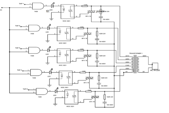
Circuitry Diagram
- The following are the components I used for this project:
– I used the AT80S8252 Microcontroller or the 89C52 which is a high performance CMOS 8bit microcomputer of sorts.
– ADC 0804 Analog to Digital Controller which feeds the input to the microcontroller. I used a step down transformer to provide samples to the ADC of the load.
-Â Zero Crossing Detector to provide the required pulses for the AND logic along with the multiplexer.
– A Multiplexer or Mux is a device that selects one of several analog or digital input signals and forwards the selected input into a single line.
In my project, the Interlocking mechanism is achieved by using Multiplexer. Thus, at any instant of time, no two triacs would be in their ON STATE. This is particularly important and advantageous in case the logic of microcontroller fails.
– I used a Liquid Crystal Display (LCD) to display the output voltage that would be across the load side.
– I used an Optocoupler MOC 3021 to transfer signals between different elements of a circuit.
CE 3.8
The following is the manner of the working of this project using a block diagram:
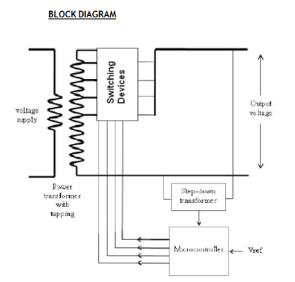
- The block diagram shows the basic strategy, as to how the Load Tap Changer will work automatically. I used TRIACs as the switching devices.
- I made sure that the The transformer has five tappings at the voltage level. Each of these tappings is connected to the one of the main terminals of the TIRAC. The second main terminals of all the five TRIACS have been shorted. So at any given time when any of the TRIAC has been switched on there is only one conducting path to the load.
- I used a step down transformer to step down the voltage level to instrumentation levels so that it can be used in the control circuitry. As the voltage increases or decreases depending on the nature of the load the voltage at the primary of the step down transformer varies, resulting in an equivalent variation at the secondary side.
- I then had to make sure that this sampled AC voltage is rectified to an almost smooth DC value. This DC voltage is then fed to the analog to digital converter, which gives a digital output that can be understood by the microcontroller. The ADC output is fed to the microcontroller which had been already programmed to compare this incoming value to a set of predefined values and send a high signal on one of its port bits. The output of the microcontroller is fed to a multiplexer. It is incorporated to ensure that at any given time, even if the logic fails there is only 1 conduction path to the load. I.e. only one TRIAC is switched on at any instance in time.
- I also used the zero crossing detector in order to detect the instance when the AC voltage crosses the zero amplitude mark. The output of this zero crossing detector is in the form a pulse generated every half cycle.
- I then fed the output of the zero crossing detector and the multiplexer to the AND logic as shown in the diagram. Each time the zero crossing detector gives an output, a pulse is generated at the output of the AND logic
- This output of the AND logic is basically our trigger signal for the switching devices i.e. the TRIACs however in order to isolate the control and high voltage circuitry and to implement DC triggering on the TRIACs operating at AC voltages the Optocouplers have been incorporated. So basically the Optocouplers are only there to provide isolation.
CE 3.9
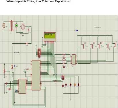
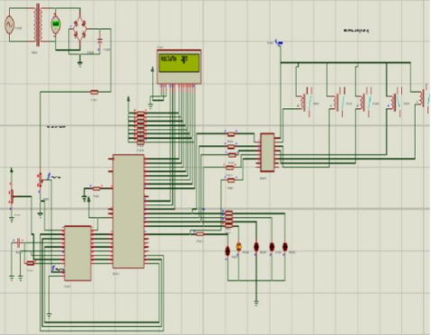
The following are simulation results I obtained:
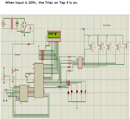
When input is 220v, the Triac on Tap 3 is on.
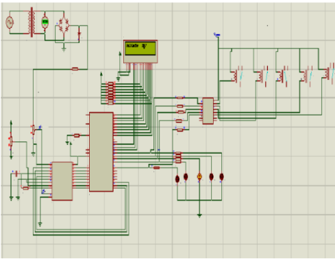
When the input is 225v, the Triac on Tap 2 is on.
- Summary
CE 3.10
I successfully completed the project titled “Design and Simulation of Automatic Load Tap Changer” along with my team mate. I learned how to build a circuit board and how all the different electrical components talk to each other in this project. I learned how important the Load Tap Changer is for any power grid and how useful it is over the Mechanical type Load type changer.
By successfully completing this project, I was able to improve my written, oral and interpersonal skills.
Cite This Work
To export a reference to this article please select a referencing stye below:
Related Services
View all


DMCA / Removal Request
If you are the original writer of this essay and no longer wish to have your work published on UKEssays.com then please click the following link to email our support team:
Request essay removal