Design of Oil Storage Tanks
| ✅ Paper Type: Free Essay | ✅ Subject: Engineering |
| ✅ Wordcount: 1767 words | ✅ Published: 24 Apr 2017 |
Oil Storage Tanks
1-Introduction
Storage tanks containing organic liquids, non organic liquids, vapours and gases are used in many industries. Most such tanks are designed and built in accordance with American Petroleum Institute API-650 specifications (1). These tanks can range in size from 2m to 60m diameter or more and are usually situated in containment basins so that spills will be contained if the tank ruptures. Storage tanks are commonly employed in industries involving petroleum production and refining, chemical and petrochemical manufacturing, bulk storage and transfer, and a variety of other industries consuming or producing liquids and vapours.
1.1-Types of storage tank
There are basically there are eight types of liquid storage tanks, viz:
(i)Fixed-Roof tanks
(ii)External floating-roof tanks
(iii)Internal floating-roof tanks
(iv)Domed external floating-roof tanks
(v)Horizontal tanks
(vi)Pressure tanks
(vii)Variable vapour-space tanks
(viii)Liquefied natural gas (LNG) tanks
The first four types of tank are cylindrical in shape with the central axis which is perpendicular to the ground. Such tanks are almost always employed above ground level. Horizontal trunks can be employed both below and above ground level. Pressure tanks are located above ground and are usually spherically shaped to provide the maximum strength to withstand high internal pressures. Variable vapour-space tanks can be spherical or cylindrical.
A containment basin made of brick or concrete is normally built around tanks with a lining impervious to the stored material in order to contain spills that could cause fire, property damage or environmental contamination. The capacity of the basin should be at least equal to that of the largest tank plus ten percent of the sum of the capacities of others.
- Fixed Roof Tanks
Fixed roof tanks are common in production facilities where it is required to store hydrocarbons with vapour pressures close to atmospheric pressure. A fixed-roof tank typically consists of a cylindrical steel shell with a dome-shaped or cone-shaped roof that is permanently fixed to the tank shell. Umbrella roofs are also common. Fixed roof tanks are used for storing very high flash-point liquids (e.g. fuel oil, water, bitumen etc.). They are generally fully welded and are now designed to be liquid and vapour tight, while older tanks with a riveted or bolted construction are not vapour tight.

Fixed roof tanks are generally insulated to prevent the risk of clogging for some materials, heating coming via steam coils inside the tanks. Dome roofs are used for tanks with a storage pressure slightly higher than atmospheric.

Fig 1. A Tank Farm showing a number of Fixed roof tanks


Fig. 2. Typical domed fixed-roof tank

Fig. 3 Umbrella fixed-roof tank
The commonest fixed-roof design has a shallow cone roof with a single centre column and internal (or external) framing to provide support for the roof plates. This involves having rafters and girders pressed to the roof radius. Cone roofs are generally supported from the shell using trusses or rafters. For large cone-roof tanks columns and girders can be used to support the roof plates and rafters.
Intermediate columns are used where the diameter is more than 37m. Designs may include a frangible roof joint (i.e. able to break into fragments when over-stressed) for added protection against a sudden increase in internal pressure. For this the design pressure limited is equivalent to the pressure of the total weight of the roof plates including structural rafters. If the storage pressures are going to exceed the capabilities of a cone-roof tant, then other fixed-roof designs such as the self-supporting dome roof or umbrella roof can be used. API Standard 650, (Appendix F) (1) designs permit internal pressures of up to 2.5 psig, depending on the tank diameter. For operating pressures of more than 2.5 psig, API Standard 620, (‘Design and Construction of Large, Low-Pressure Storage Tanks’) (2) has design procedures for internal pressures of up to 15 psig.
Because of environmental concerns and to cut down on vapour losses designs tend to include internal floating decks in fixed roof tanks either at the time of construction or later as a retrofit (Fig 3). This has the advantages of both fixed and floating roof design.
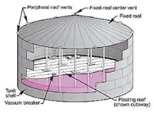
Fig. 3. Domed fixed-roof tank with inner floating roof
and showing roof supports
Emissions from fixed roof tanks vary depending on vessel capacity, utilization rate of the tank, vapour pressure of the stored liquid and the local atmospheric conditions. Losses of the stored product from evaporation can be large in fixed roof tanks – particularly for crude oil where vapours are released through the pressure vent valve. Losses are classed either as Breathing Losses or as Working Losses. Breathing losses occur when vapour expansion and contraction caused by changes in temperature and atmospheric pressure lead to the expulsion of vapor. This loss happens without any change to the liquid level in the tank. Working losses happen when the liquid level in the tank is increased. Fixed roof tanks are either freely vented or have a pressure/vacuum vent that allows the tank to operate at a slight internal vacuum or pressure. This stops the release of vapours when there are very small changes in pressure, temperature or to the liquid level. It is also possible to make tanks that are inert when there is a slightly positive gas pressure. Such tanks should have pressure-vacuum valves and when in use be purged with natural gas to remove air from the vapour space.
|
Type |
Advantages |
Disadvantages |
|
Self-Supported Cone Roof |
Minimum internal obstructions Relatively cheap Suitable for internal protective coating Cost-efficient conversion to floating roof if needed |
May need a heavy roof deck plate Only suitable for small tanks |
|
Centre-Supported Cone Roof |
Simple structural design Minimum internal obstructions Relatively inexpensive Cost-efficient conversion to floating roof if needed |
Less ideal for protective internal coating Tank diameter limited by span of rafters in roof |
|
Multiple-Column Supported Cone Roof |
Simple structural design Relatively inexpensive Suitable for any diameter tank Can be frangible for emergency venting |
Poor for protective internal coating Many internal obstructions Difficult to inspect Requires costly conversion to internal floating roof if required |
|
Externally Supported Cone Roof |
Minimum internal obstructions Relatively inexpensive Suitable for internal protective coating Cost-efficient conversion to floating roof if necessary |
May require heavy roof deck plate Only suitable for smaller tanks Less ideal for protective internal coasting Roof more expensive than internal supported roof Is not frangible |
|
Dome or Umbrella Roof |
Excellent design for internal protective coating Excellent design for highly corrosive materials |
More expensive than cone roof Suitable for only small and medium tanks Roof deck plate is the only structural support Not suitable for high vapour pressure stocks Is not frangible |
Table 1 Advantages and disadvantages of different types of fixed-roof storage tanks (5)
2.1Gauge Hatches
Fixed-roof tanks should have a gauge hatch in the roof which allows it to be opened quickly. This allows the operator rapid access to “gauge” the tank. Gauging comprised:
- measuring the volume of liquid in the tank
- finding out if water is present and, if so, measuring the height of the oil/water boundary
- sampling the material in the tank.
- determining the temperature of the liquid in the tank.
The gauge hatch can be weighted so that it will work as a backup pressure or pressure-vacuum relief device to complement the primary pressure-vacuum valve.

Fig 3 – Typical gauge hatch
Standards for the manual gauging of petroleum and its products are contained in the API Manual of Petroleum Measurement Standards (3).
2.2Filling or pumping operations
Routine tank filling and pumping will affect the vapour space in a fixed-roof tank. Removing product from the tank draws air into the vapour space, creating a hazard. During the holding period prior to refilling the tank, evaporative breathing losses are increased because of the larger volume of the vapor space. Adding product to the tank, increasing the volume of liquid, displaces the the mixture of air and product vapour via the tank vent, causing significant evaporative emissions.
2.3Gas blanketing systems
If the vapour pressure of the product in the tank is low (below 10kPa), it is safe practice to use a freely ventilated fixed-roof tank. For production tanks or other applications where the vapour pressure of the incoming liquid is usually higher than atmospheric pressure at usual ambient temperatures, a gas blanketing system is needed to maintain positive tank pressure and minimise the risk of air being sucked into the tank vapour space. At times when there is no inflow of product, the tank breathing process could, by itself, lead to air being drawn into the tank through the pressure-vacuum valve, forming a potentially explosive mixture.
A gas blanketing system needs a supply of natural gas and a pressure regulator that works to keep the tank pressure at the desired level. When the ambient temperatures increase causing the pressure inside the tank rise, the regulator closes. If pressure continues to rise, the
pressure vent opens to relieve the internal pressure in the tank by venting vapours (blanket gas plus product vapour) to the atmosphere or to some vapour recovery process. A vacuum relief valve must still be used to protect the tank against a vacuum forming if the gas blanketing system should fail.
2.4Fire Exposure
Out breathing, caused by exposure to fire, may exceed the design venting rate based on normal operating conditions. If that happens, the tank’s construction details determine whether additional venting is needed.
On fixed-roof tanks, where the roof-shell attachment is constructed according to API Standard 650 (1), the roof-to-shell joint may be considered frangible, so that excessive internal pressure may cause it to fail before failure occurs in either the tank-shell joints or in the shell-to-bottom joint. In tanks built in this way, there is no need for addition emergency venting systems, as long as the tank is well away from other equipment and the loss of the roof in an emergency is acceptable.
On tanks that do not have frangible joints, design procedures are given in API Standard 2000 (4) for calculating the necessary venting capacity for fire exposure.
2.5Containment Basin
Fixed roof tanks are constructed insida a containment basin made of brick or concrete and with a lining that should be impervious to the liquid being stored to prevent spills that can cause fire, property damage or environmental contamination. The minimum capacity of the basin should equal the capacity of the largest tank plus 10% of the combined total capacity of any others. To contain a spill or to prevent some other emergency the basin walls must be able to withstand high pressures and also be resistant to the stored product. The basin drain valve is put into the outer side of the containment basin and must normally be kept closed to prevent possible leakage of any contaminant into the environment.
Cite This Work
To export a reference to this article please select a referencing stye below:
Related Services
View all


DMCA / Removal Request
If you are the original writer of this essay and no longer wish to have your work published on UKEssays.com then please click the following link to email our support team:
Request essay removal